Problem with Voltage range selection #9
Description
This has been manually split from #7
[marianomd]
This is stopping me from using this great piece of software. Furthermore, I already rewired the encoder, so for the time being I have a paperweight. I'm on FNIRSI.
[mean00]
BTW you can easily revert the rotary encoder change
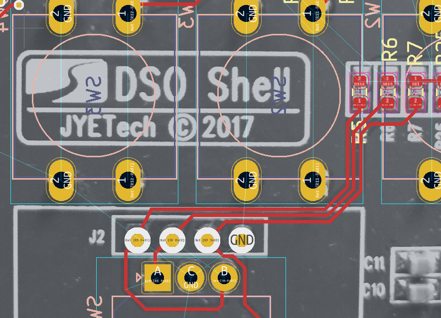
https://user-images.githubusercontent.com/8426909/243091951-295a699b-577f-48be-8f14-84da3012ba1d.png
Just connect the 2 modified pins of the rotary encoder to the bottom side of R5 and R6
You can then switch easily between the 2 configurations
Also it would be interesting to get the voltage on the ASM117 chip
It should be 3.3v
Attached is a test fw for FNIRSI
Could you report the number at the bottom right ?
It should be around 3300.0
[marianomd]
Measured voltage with multimeter on AMS1117: 3.316v
Run the binary, here is the shot:
[mean00]
Thanks
The VCCA is off by 5% much less than the error, so there's something else
Could you take a picture of the analog board (the one with the BNC connector) to check the resistor values ?
[marionomd]
Let me tell you my error:
3.31 are read as 3.25 - 3.27 (good!)
5.05 V are read as 4.95 - 5.06 (good!)
10V are read as 9.59V
20V are read as 9.59V
28V are read as 9.59V
It's like capped !
Seems to be not exactly the same problem as OP.
[mean00]
Thanks for the image.
yes it looks like saturation
I just tried on mine and i can go at least up to 18V without problem
Might be interesting to check the voltage on pin 9 10 and 11 of the 74HC4051 when you use 1v and 5v
They are the command pins to select the input gain/attenuation
They are also available on the interboard connector, easier to check
[marianomd]
It's always the same, tested with 1, 5 and 10V.
SENSE0: 0
SENSE1: 0
SENSE2: 3.3
SENSE3: 0
[mean00]
Ok, that's the problem
Let me double check on my end but i think it worked last time i checked
tested on my FNRISI unit
1v : 0 0 1 0
2v : 0 1 1 0
5v: 1 1 1 0
So in your case it seems to be stuck at the 1v setting
[marianomd]
What does that mean? Can it be corrected by software?
Could you try with the attached version ?
Are the others voltage ranges working fine ? In particular 10mv,
fnirsi_const.zip
20mv and 50mv/div ?
Thanks for the follow up.
Mode: DC
1 V: down to 100 mV range, reading is correct, less is wrong (50 mV reads 381 mV, 20 mV reads 191 mV, 10 and 5 mV read 96 mV)
2 V: down to 500 mV range, reading is correct, less is wrong (200 mV reads 1.42 V, 100 mV read 0.95 V, less ranges same as above)
5 V: exactly the same as 2 V.
10 V: reads OK down to 2V range. 1V and 500mV ranges give 9.50 V. 200mV and down, same as above)
20 V: reads OK (19.53-19.72) at 5V range. On 2V range it gives 19.01V, on 1V range it gives 9.50V (same as above all the way down)
Seems the reads are ok if the waveform is on screen. When it goes offscreen it is capped.
[mean00]
It looks like the command signal to switch voltage range is not working
These are the SENSL0...3 pins
If it behaves the same without the analog board, it points to either a different board layout (unlikely) or a damaged chip (?)
Thanks a lot!
Now I know how to get a valid reading, by setting the correct range. It's not clear if this can be done on the official release, or only in the bin you sent me.
[mean00]
You can check with any version, it's the way the hw is wired