Concept PokemonGo Plus modify and Arduino controller board.
- Develop stage
- Contents
- WARNING
- Files and folders
- Circuit diagram and PCB design
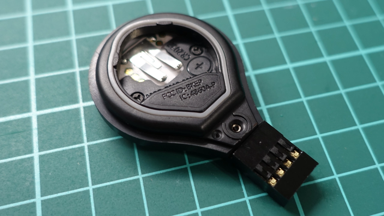
- Teardown Pokemon Go Plus
- Pirated version Pokemon Go Plus
- Modify Pokemon Go Plus
- Soldering components on control board
- Connecting cable for Pokemon Go Plus
- Compile Arduino code and upload
- Demo video
- Bill of materials
- Tips
- Required tools
- Copyright clearance
- Resources and great thanks
- Concept only, not recommended for new builders anymore.
- Modify PGP could be damage, or lead to unrecoverable damage.
+ Please make sure you have required tools and sufficient knowledge about electronicsarduino_codeconcept_reference.inoClean copy fromJohan von Konow
bill_of_materialsconcept_bom.pdfAbout PCB design, and bill of materials
action_of_pokemon_go_plus.mdExplane the mechanism of Pokemon Go Plusconcept_gerber_arduino_nano_v1.zipConcept PCB design for Arduino Nanoconcept_gerber_arduino_nano_v2.zipEnhanced concept PCB designconcept_gerber_arduino_uno_v1.zipConcept PCB for Arduino Uno
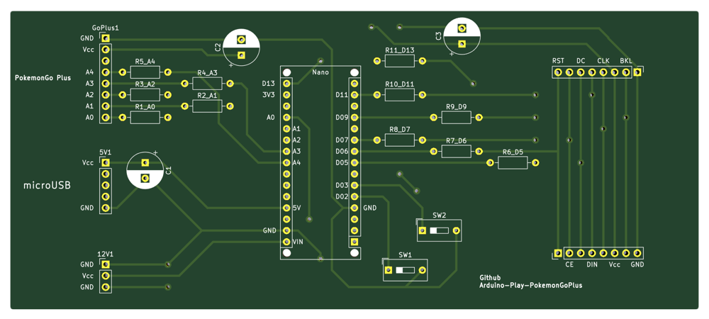
- Circuit diagram
- Concept PCB design for Arduino Nano
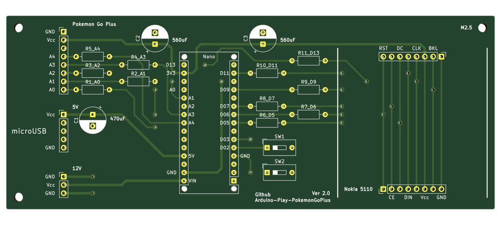
- Enhanced version
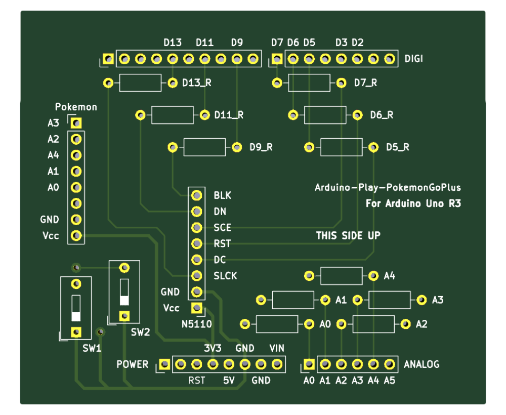
- For Arduino Uno

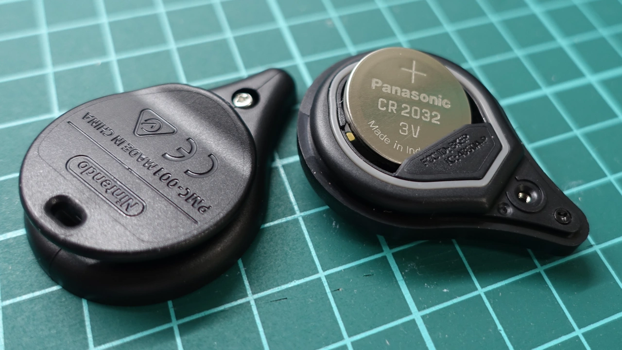
- Remove CR2032 battery from Pokemon Go Plus
- Using Y00 triwing tripoint screwdriver to
- Desoldering vibration motor
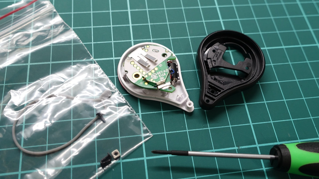
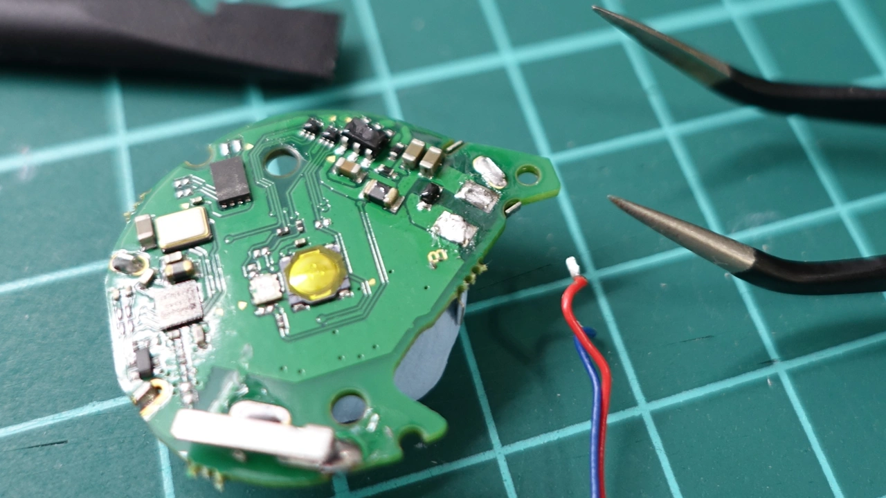
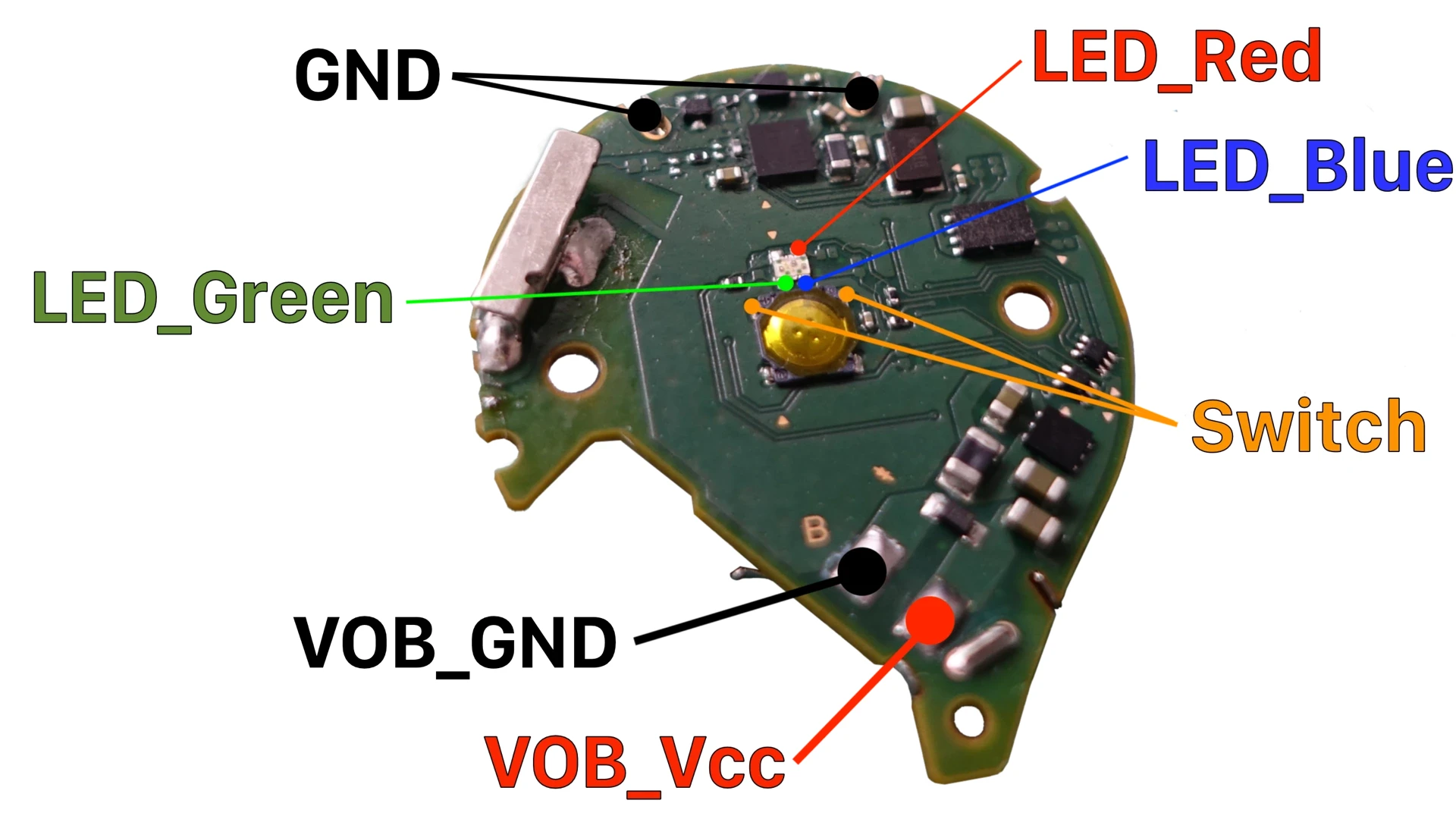
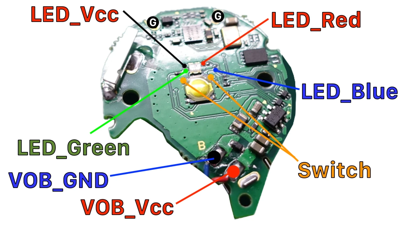
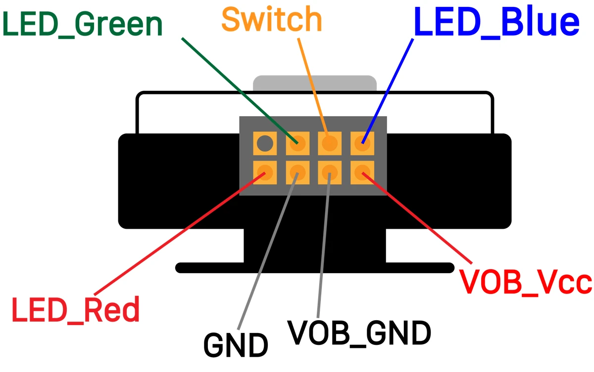
- Figure out pinout.
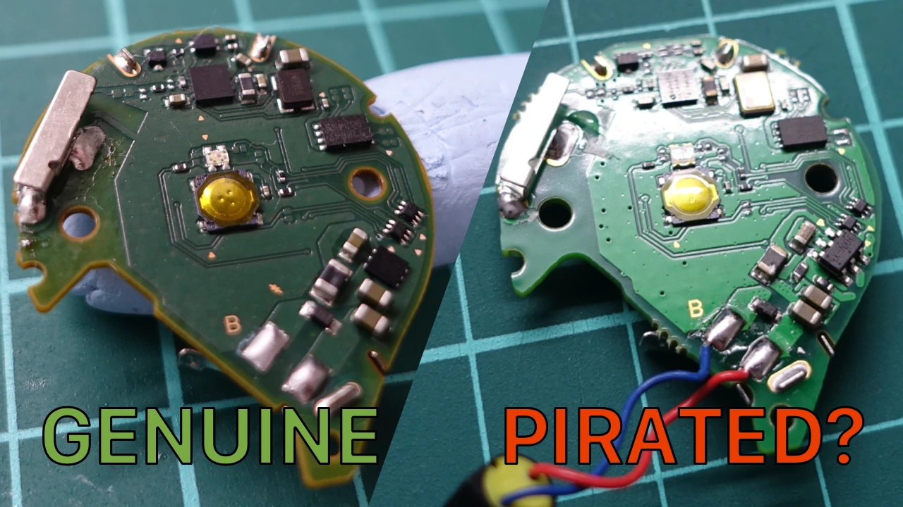
- Unfortunately, after teardown more Pokemon Go Plus, I thought that I bought pirated version.
- Fortunately, the pirated version pinout is same as genuine version.
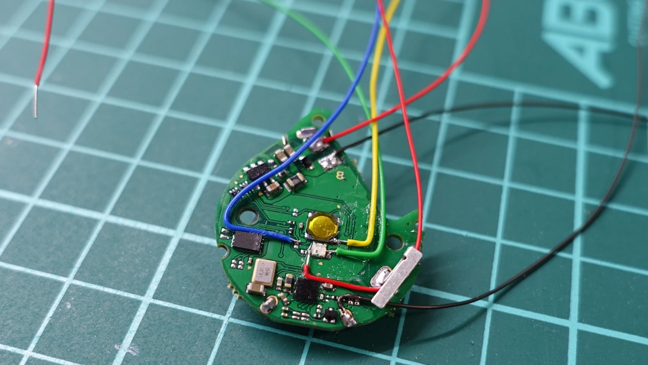
- Soldering 30AWG wire wrapping wire, it should stretch seven connect wires, then fixed the wire.
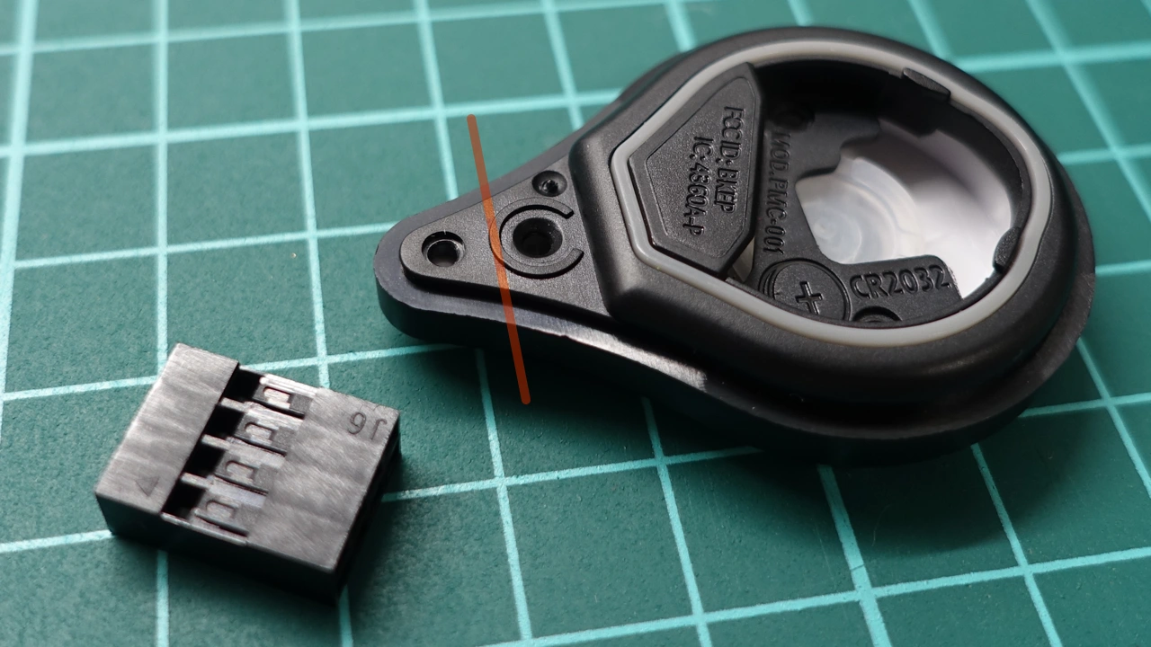
- Cutting Pokemon Go Plus case, for setting pin connector.
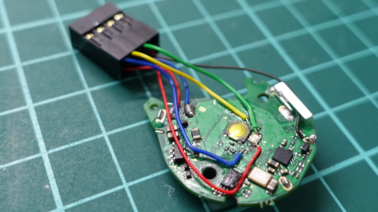
- Connecting circuit from Pokemon Go Plus to pin connector.
- Pinout and circuit rule as follows.
- Fixed the pin connector, then put everything back, without vibration motor.
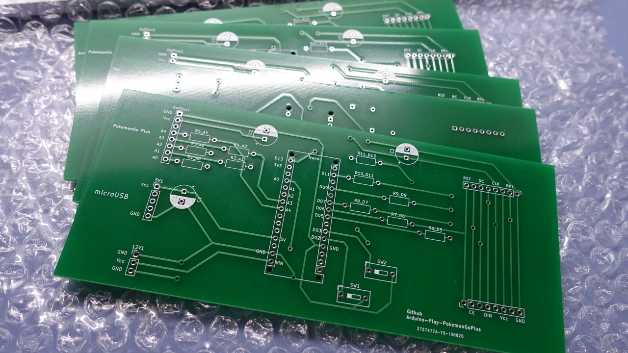
Download Gerber file, Upload to PCB prototype manufacturer, or PCB fabrication manufacturer.
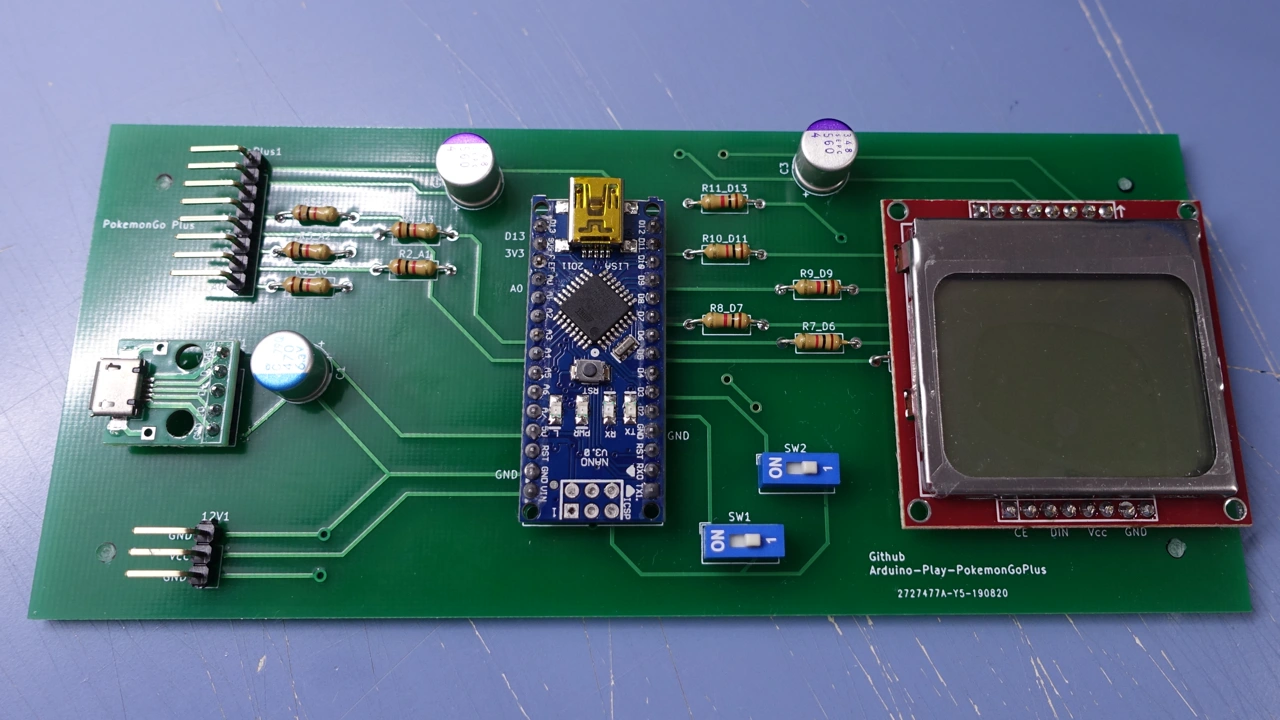
- Get PCB from PCB fabrication manufacturer, or PCB prototype manufacturer.
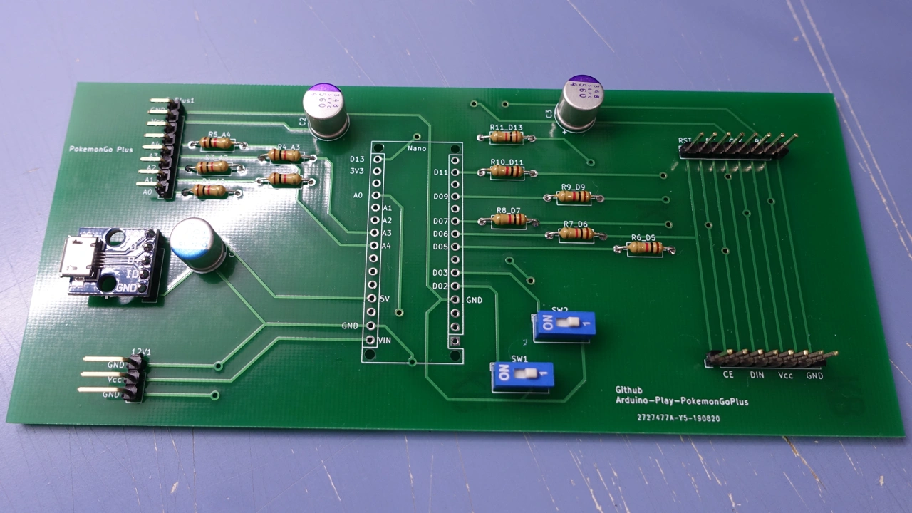
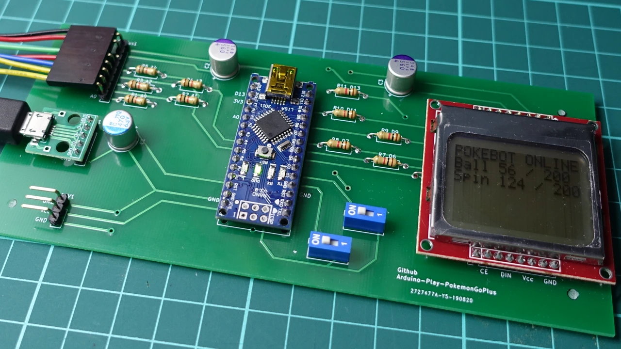
- Soldering electronic components, including pin header, capacitor, slide switch and micro USB breakout board.
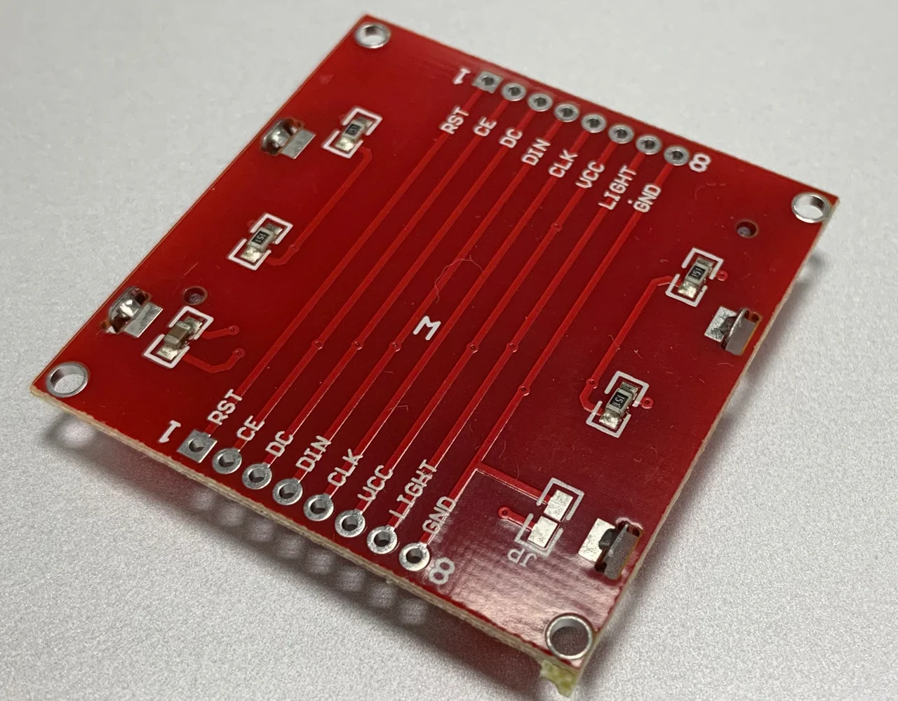
- Checking Nokia 5110 LCD Board pinout, make sure it can directly connect to board or need wire.
- If the backlight circuit already has resistors,
Resistors R9_D9don't need to install, soldering as jumper. - Soldering Nokia 5110 LCD Board, or using pin header and pin connector
- Soldering Arduino Nano, or you can soldering pin socket, so you can remove it easily.
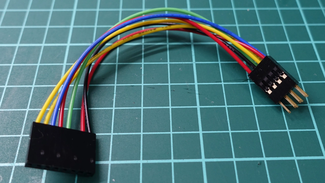
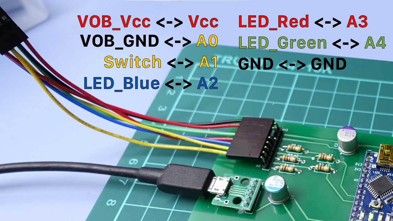
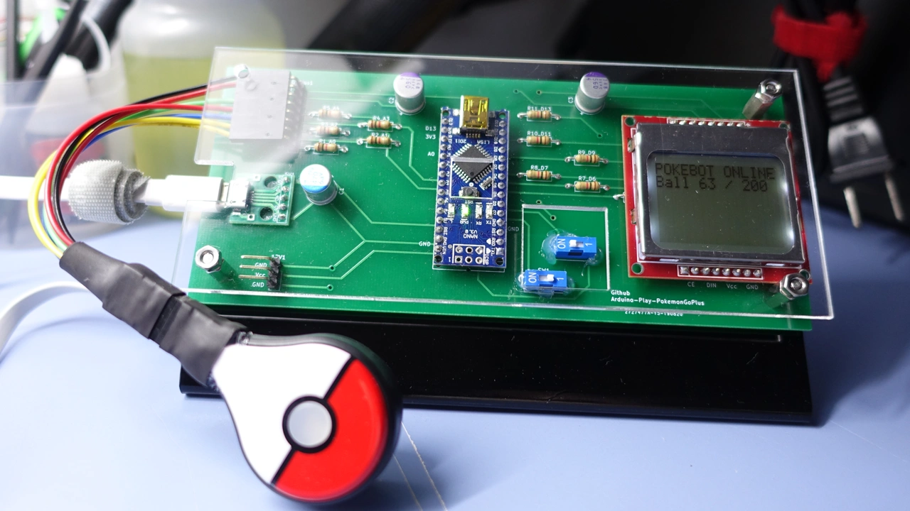
- Making Pokemon Go Plus connect cable.
- Pinout and circuit rule as follows.
- Plug Arduino USB cable, compile and upload program.
- Power on the Board, Connect Pokemon Go Plus.
- Pray that everything goes well
- Now, enjoy
bill_of_materials/concept_bom.md
- Using
ML2032rechargeable coin battery replaceCR2032, Then it can be charge by Arduino. - Make a simple board including battery, and DIP Switch that can short-circuit VOB_GND and Switch,
Auto Click !.
- Y00 triwing tripoint screwdriver ( teardown Pokemon Go Plus )
- Pin clamping pliers
- Soldering iron
- Liquid soldering flux
- 30AWG wire wrapping wire ( silver plated wire ), or enamelled wire
- 24AWG stranded conductors wire
- Super glue or UV light glue
- Hot glue gun
Arduino code was copy from Johan von Konow wbsite.
Concept arduino code and circuit design reference from Johan von Konow
PokeBot – Catch Pokémon’s in your sleep (and at work) Written by Johan von Konow