Hello, World!
I settled down to a ICE40UP5K-SG48I since it has a QFN package and an OK number of LUTs
Found a crystal suitable for the fpga, and started building the power rails.
I also tried making a power supply filter, but I can't seem to add ferrite beads to the schematic (I'm using Easyeda Pro).

INSANE rp2350 && ice40 schematic speedrunning session
Just mostly need to get the 40-pin connector in-place
I still have to find the perfect ferrite bead


By the way, you might be wondering what are those strangely-routed USB and USBc female ports are for, and I will be using those to see if I can make my own TCP/IP stack on the fpga, as a nice side-quest.
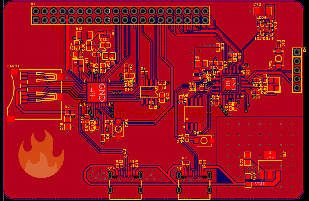
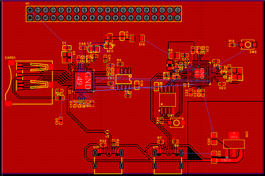
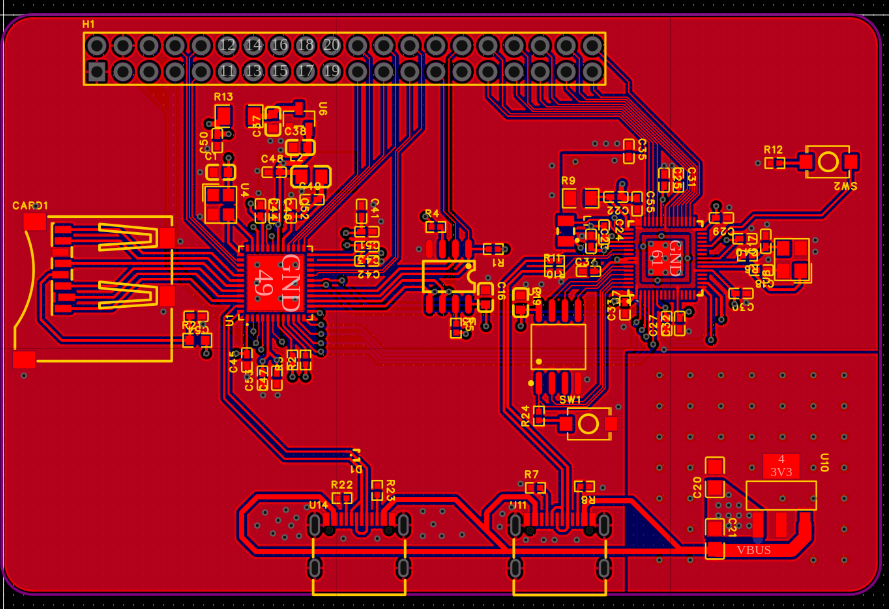
Today I changed switched of my capacitors to be 0402, I also placed the components on the pcb and routed them, for the most part.
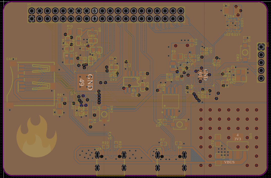
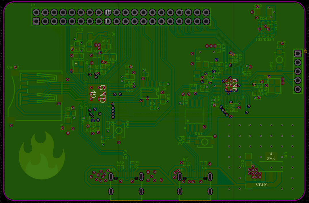
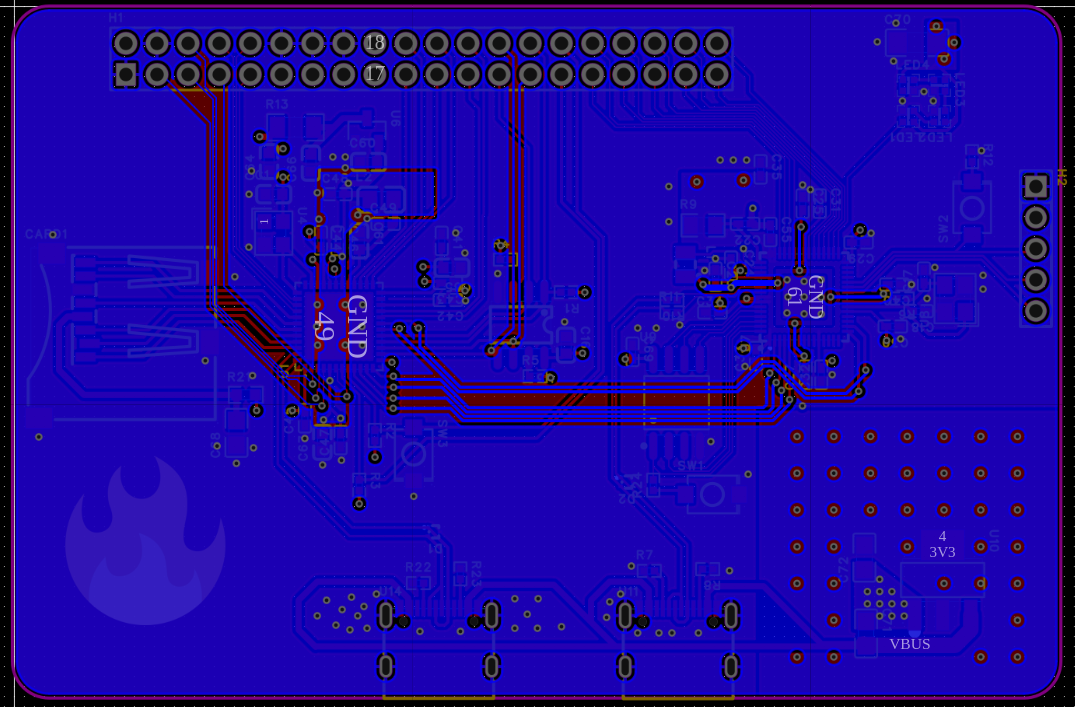
I also decided I will use a 4 layer board with Signal-GND-3v3?-Signal layout. I have a few doubts if I have positioned the inductors for the rp2350 regulator correctly Did some of the work in class because I was bored =D
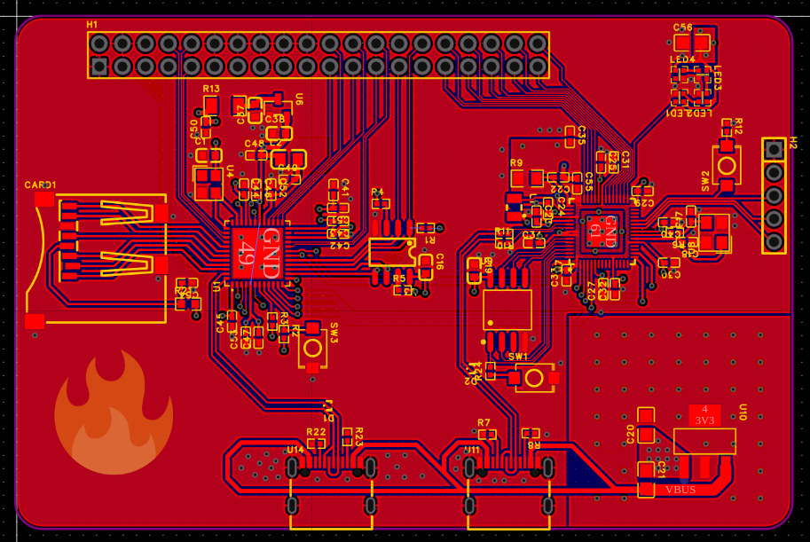
Hi fellow readers, today I added 4 small neopixels on the top-right of my board, fixed some of my extremely janky routing for the headers, added some debug headers for the rp2350 and a button to reset the ice40.
I am most likely finished with this board, just needs some polishing and some silkscreen art :)